The Genii Hack
This is not really a Tesla-related project, but it is related to the previously described Garage Minder effort. Moreover, it is not truly a hack since it does not intrusively modify the product.
This note describes a method to indicate when a car entering a garage has pulled in sufficiently. The driver should stop when the red LED in the Genii wall console comes on.
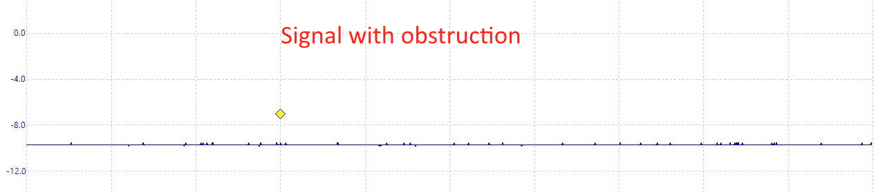
We recently replaced our old garage door opener with a basic Genii belt drive unit. The new opener is very quiet and works well with the Garage Minder controls. It has a feature called Safe-T-Beam which must be installed for the opener to function. It transmits an IR beam across the doorway to a matching receiver and an obstruction is detected whenever the beam is blocked. I really didn't want this feature and hate it when vendors try to impose their philosophies on me, though I must admit that it is very well designed for idiot-proof installations. The Internet provides many lame suggestions for how to bypass it, typically by sticking the receiver and transmitter together. I eventually found one useful article about it by "Joel Ideas". Joel also proposes a really elegant way to bypass the system. It turns out that the IR receiver generates an active signal on the sensor wires. This signal needs to be simulated to bypass the sensor. Simply disconnecting the wires or shorting them will not suffice. On the Genii model I have, the signal is a 330 Hz square wave with voltage levels ranging from 9V to 3V, as shown below. When the beam is interrupted, the signal is a flat 9V level, as shown. It appears that the IR receiver is pulling the 9V down to 3V whenever it senses the IR beam. The trace is shown inverted only because the striped sensor wire that Genii calls positive is at a lower voltage level.

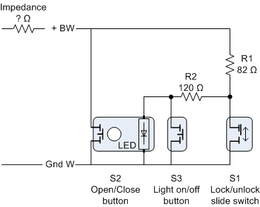
I also investigated the voltage levels on the "Wall Console". Besides the button to open/close the door, there is a switch to lock the door and a button to toggle the light on/off. The circuit is shown below. Once I understood the opener's design, I got ideas for new features.
|
Condition |
BW to Gnd |
Notes |
|
Disconnected |
5.15 V |
Full voltage, no LED lit |
|
LED lit |
3.65 V |
Wall Console connected, LED on |
|
S2 pressed |
0 V |
As expected, shorted |
|
S1 (Lock) on |
0.79 V |
Calculated outimpedance = 453 Ω |
|
S3 (Light) pressed |
1.94 V |
Calculated out impedance = 334 Ω |
Stop Light
A visible Stop indicator in the garage is useful to indicate when to stop driving forward while parking. The Safe-T-Beam detects when the vehicle is completely inside the garage. We had a tennis ball hanging from the ceiling to indicate this. It is a pretty simple idea, but our doggie always wanted that ball. I wanted a red light to come on to indicate when the back end of the vehicle cleared the Safe-T-Beam.
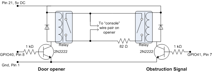
The red LED in the Wall Console button was an obvious choice for the Stop light. According to the Wall Console circuit, the LED can be turned on and off by placing an 82 ohm resistor across the console wire pair. The Garage Minder already had access to these wires. Next, we need to filter the wave from the obstruction sensor to yield a useful TTL signal. To shape the wave, a 0.1uF capacitor eliminates the DC offset. The diode blocks the negative spike. The 4.7uF capacitor acts as a charge tank and the 82K resistor drains the tank. The resulting signal is suitable for the processor; it is high (2.7v) while there is no obstruction and low when there is an obstruction and no AC waves. When the signal is low, then a relay triggered causing the red LED "Stop light" to come on.

In the wave form shown above (Signal with no obstruction), note that the upward trace is much steeper than the downward line. This causes a higher spike through the 0.1uF capacitor, thus avoiding the need to amplify the resulting output with a transistor.
Patent
A quick search found the following abandoned patent Garage parking assistant (US20100245127A1) which seems close. The difference is that this note describes a method to use the existing sensor, wiring and indicator. I sent Genii a note but never heard back. They could easily add this feature at no cost.
Acknowledgments
Many thanks to Joel for the initial idea. You da dude. Long may you live.
Also, thanks to Pico Technology for making the really cool PC-based oscilloscope.
All in fun
Sept 2021