The Cuisinart Air Fryer Hack
Background
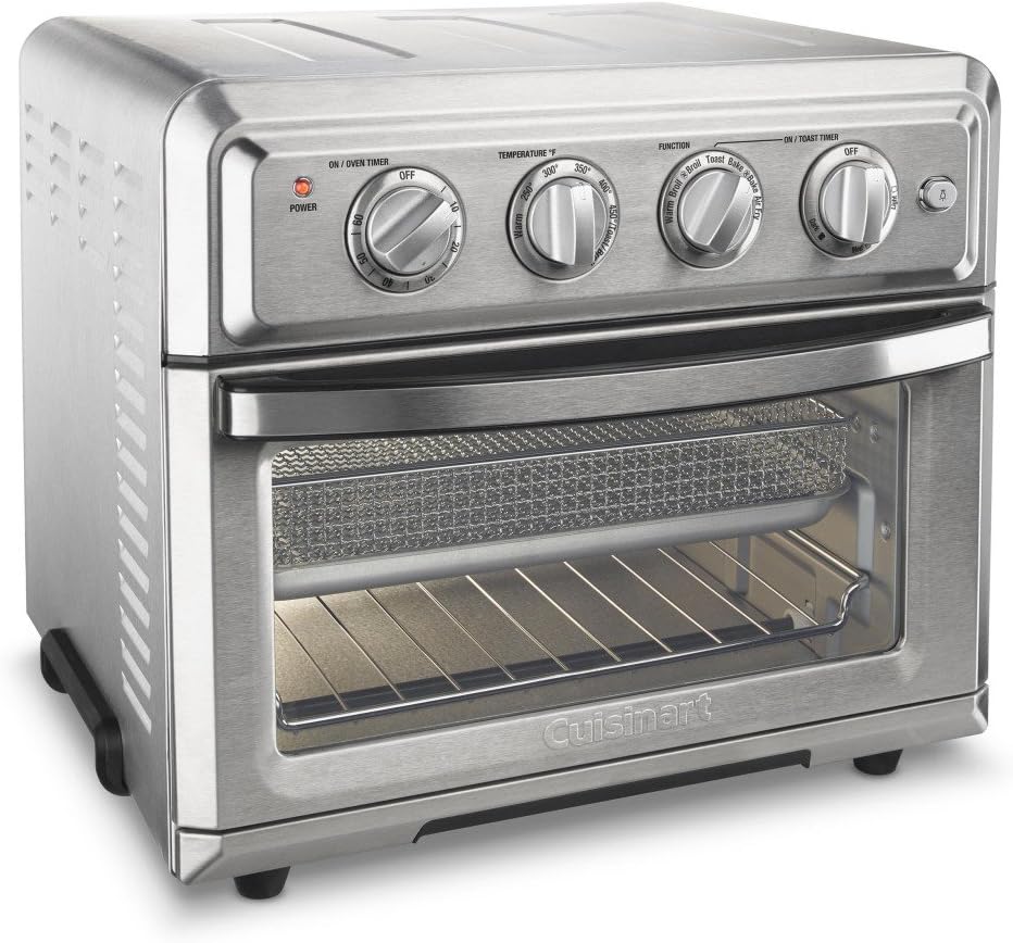
Our toaster was toast. The Cuisinart Toaster Oven Air Fryer TOA-60 died after about 1 year and a half of active use. The function selector had burned out due to arcing. The door switch also showed signs of arcing. Cuisinart cheerfully replaced the unit under warranty, but that left the old stainless steel hulk sitting around. This project rebuilt it using a Raspberry Pi and allows it be controlled from anywhere across the Internet. Feel free to skip the disassembly and discovery in Part 1 and read the new design in Part 2. Click on any picture to expand it.
Part 1: Understanding the Toaster
Disassembly
The first goal is to get the stainless steel cover off. We need a 10" long Phillips screwdriver, a large flat head screwdriver, a set of Allen hex keys and a headlight. This process takes about an hour. Click on the hyperlinks below to see pictures.
1. Remove the grill and the crumb trays.
2. Remove the back.
a. There are more than 12 screws holding the back.
b. One of the screws needs an Allen key for removal.
3. Remove the left plastic foot assembly.
a. There are 3 conical head screws.
4. Remove the right foot assembly.
a. Pop off the 2 rubber covers on the right assembly. Use the handy Allen key.
b. Remove the 2 round head screws inside the foot.
c. Remove 1 conical head screw in the middle.
d. Keep these screws separate from the others.
5. Next reach through the back opening to remove 8 screws that are on the front.
a. You will need the long Phillips head screwdriver. Magnetic tips will help.
6. There are 3 spring clips on each side of the stainless steel cover. They attach the cover to a flange in the front.
a. The clips are built into the outside cover.
b. Use a flat head screwdriver to gently force the cover backward off the clips.
c. The cover is now free. The components are exposed.
7. Put the 2 plastic feet back on to avoid scratching your dining table.
a. Note that the screws for the left and right feet are different.
8. Next, you could grasp the function knob and pull it straight out. It may be tightly fit.
a. You can see the 2 screws that mount the rotary switch. It just brings you the satisfaction knowing that if you had a replacement part, you could fix this thing. Cuisinart may not sell a replacement.
b. If a replacement is not available, don't bother with this step. You can leave the switch as a non-functional ornament. Removing it will leave an ugly hole.
9. Here are some pictures
a. the left side,
c. right side, this is where all the action is,
d. top, another top, yet another top,
f. light switch,
g. door switch, and another of the door switch.
Tracing the wiring
The red, white and blue colors of the wires seem to be chosen without a strategy. Tracing the spaghetti reveals the following schematic. Personally, I would have placed the thermostat along the wire marked "Timer gated power", allowing the heater elements to be grounded directly to neutral. But no big deal. The Microtemp thermal fuse is rated to blow at a specific temperature (marked 216°C, 420°F).

Rotary function selector
The function selector gadget seems to be a proprietary Cuisinart specified part that is sourced by a Chinese vendor. A replacement may not be easily available. Similar parts are listed on eBay with the same part number, but they are nowhere near usable. The original part can be described as a 4 pole, 7 position, multi throw rotary switch, and it is the heart and brains of this toaster. It comprises two rotary modules stuck together concentrically, and each module has 2 switches. Let's call the 2 modules Front and Back. Front contains switches A and B, and Back contains C and D. Each switch has one input and two outputs, except B has only one output. Depending on the position, each input connects to none, 1 or 2 of its corresponding outputs.
The following table shows its connectivity. There are 4 inputs: A, B, C and D. There are 7 outputs: A1, A2, B1, C1, C2, D1 & D2. The check marks indicate if the input is connected to the output at that position. Heater elements are in red, fans are blue, timers are black. For example, in the position Toast (position 4), input A connects to both A1 &A2, input B connects to B1, and input D connects to D2. This effectively turns on A1 (fan in low), A2 (upper outer heating element), B1 (lower heating element) and D2 (engages the toaster timer). The 'Warm' setting activates the lower heater element. Interestingly, 'Bake' & 'Toast' are identical, as are 'Broil w/fan' & 'Air-fry'.
|
Switch à |
Front Module |
Back Module |
||||||
|
Input à |
A |
B |
C |
D |
||||
|
1. Warm |
|
|
ü |
|
|
|
ü |
|
|
2. Broil |
ü |
ü |
|
|
ü |
|
ü |
|
|
3. Broil w/fan |
|
ü |
|
|
ü |
ü |
ü |
|
|
4. Toast |
ü |
ü |
ü |
|
|
|
|
ü |
|
5. Bake |
ü |
ü |
ü |
|
|
|
ü |
|
|
6. Bake w/ fan |
|
ü |
ü |
|
|
ü |
ü |
|
|
7. Air Fry |
|
ü |
|
|
ü |
ü |
ü |
|
|
Output à |
A1 |
A2 |
B1 |
|
C1 |
C2 |
D1 |
D2 |
|
Targetà Component |
Fan Low |
Up Out |
Low Htr |
|
Up In |
Fan High |
Oven Timer |
Toast Timer |
Air Fry function
The Air Fryer has a two speed fan to circulate hot air inside the chamber. The fan also expels some air from the chamber, thus cooling it down. Extra heat is needed to maintain the temperature while the fan is on.
Power Measurements
After they were disconnected, the 3 heater elements were measured: Upper Outer=16 Ω, Upper Inner = 17.4 Ω and Lower = 17.3 Ω. At most two elements will be on at any time. The fan consumes 35W. So the maximum device consumption is about 15 amps, or 1800W, as specified.
Temperature Control
The original toaster uses a thermostat. This is a mechanical device that consists of a dial to select the desired temperature, a temperature sensor and an on/off switch. Its job is to control power to the heater elements so that the oven reaches and maintains at the desired temperature setting. The following graph shows its operation at a set point of 300°F. The red line displays the actual temperature swinging between 250° and 400°F. The green trace shows the heater elements coming on and off. While the average temperature is 300°F, the temperature swings are excessive and lead to food getting burnt.

Part 2: The New Design
Requirements for a New Design
Engineers always list the requirements before starting a design. It's the marketing guys that keep changing the requirements. Here is the initial list:
1. Backward compatibility with current functionality using the existing mechanical timers. It should work intuitively for the non-geeks. The timers and temperature control should work as expected. The function selector, which is broken, is exempt from this requirement.
2. Use a digital thermometer since the original thermostat is inaccurate and causes large temperature swings. Temperature excursions should be limited to ±5°F.
3. Add more heating modes for Warm and Slow cook functions. The three heating elements can be configured to provide fine temperature controls.
4. Multi-step program operations, like: Preheat, then Bake at 350° for 30 minutes, cool down to 250°, then Broil for 5 minutes and keep warm till 6PM.
5. Delayed start and Pause options.
6. Browser-based GUI to select oven function, temperature, duration, etc. Integration with external applications via a REST API.
7. Voice control and voice notifications, and automated home integration using Alexa.
8. A nominal buzzer, although voice responses may be more suitable.
9. SMS text notification, for completion of each program step.
10. Touch-sensitive LCD screen for control, though a web page will also be available.
11. Moisture sensor, to prevent burning and to implement a dehydrator.
12. Camera for visually checking the doneness of food, say "Toast till brown", or "Broil till bubbly".
13. Smoke detector, to help decide when to give up the toast and automatically order a pizza, just kidding.
New Hardware Design
At a high level, a Raspberry Pi Zero 1 W uses 8 of its GPIO pins to control 8 relays. The relays drive the toaster's three heater elements, fan and lights. Besides turning on each element at full power, the relays can also configure them in series to allow for gentle warming. Five other GPIO pins are used to sense the state of timers, thermostat and switches. Three more GPIO pins for the thermometer. A web server on the Pi listens for commands via Wi-Fi. It also drives an LCD screen and serves up REST APIs for basic commands.

The control part is fairly straightforward. A 8 channel current booster (ULN2803A) is used to drive the relays. This wonderful chip contains all the necessary transistors and no additional components are needed. It requires the +5V lead (COM) to dump flyback currents from the relays. The ULN2803A connects very nicely to the relay module.

The low voltage section for sensors is wired separately. A 5 Vdc power supply is added inside the toaster shell. The Raspberry Pi is installed on the fan housing. The metal oven outer casing will be replaced to avoid blocking WiFi signals and to allow better cooling for the new components. It will also show off the cool tech. Ribbon cables connect the Pi to relays and sensors.
Temperature Measurement
A thermocouple is added to measure the actual instantaneous temperature. It consists of two components: a MAX6675 IC and a K-Junction thermocouple. The first thermocouple I tried had problems.
· Measurements showed that the thermocouple had a very poor response time and lagged the actual temperature. This was because the thermocouple was firmly bolted to the toaster walls and effectively had a large 'thermal mass'. The metal surrounding the thermocouple took a long time to reach the temperature of the air in the oven.
· The following graph illustrates this. The oven is already warm and is maintaining the set point of 200°F. The green plot is the heater element turning on and off, and the red plot is the thermocouple reading. The heater goes on at about the 865 sec mark, but the reading is still dropping. The reading starts to rise around the 910 sec mark. The heater goes off at the 940 sec mark, but the reading continues to increase till the 1020 sec mark. Again, this measurement used the thermocouple for temperature control. Note that the average temperature is higher than the expected 200°F and the range is between 190 to 225°F.

A smaller thermocouple was used and it has a much better response. The ambient temperature is tracked while the oven is not being used.
A MAX31856 converter was tested, but the benefits were not clear. A MAX6675 with Hardware SPI was adequate for the job.
Relay based control (deprecated)
The relays were initially wired as shown below. Two of the relays (R1 & R2) were used to string heater elements in series. This allowed for heating with lower wattages. The table below shows the power and relay settings for each element combination. There are 11 combinations, of which 4 are suitable for broiling. However, this element chaining feature was not sufficiently effective, and there was a lot of relay clicking.
The relays also allow three settings for the fan: high, low and off. The fans greatly affect the heating and cooling rates and affect the temperature control logic.

|
Combination |
Resistance (Ohms) |
Power (Watts) |
Relays |
Mode |
Function |
|
Lower + Upper Out |
8.31 |
1732 |
R4, R5 |
Oven |
Bake |
|
Lower + Upper In |
8.67 |
1660 |
R4, R5 |
Oven |
Toast |
|
Lower + (Upper Out -> Upper In) |
11.40 |
1264 |
R5, R6, R1 |
Oven |
Brown |
|
(Lower -> Upper Out) + Upper In |
11.43 |
1260 |
R5, R2, R4 |
Oven |
Roast |
|
Lower -> Upper Out |
33.30 |
432 |
R5, R2 |
Oven |
AirDry |
|
Lower -> Upper Out -> Upper In |
50.70 |
284 |
R5, R2, R1 |
Oven |
Warm |
|
Upper Out + Upper In |
8.34 |
1728 |
R4, R6 |
Air-Fry |
Broil |
|
Upper Out |
16.00 |
900 |
R6 |
Air-Fry |
Brown |
|
Upper In |
17.40 |
828 |
R4 |
Air-Fry |
Toast |
|
Upper Out -> Upper In |
33.40 |
431 |
R6, R1 |
Air-Fry |
Warm |
|
Lower |
17.30 |
832 |
R5 |
Grill |
Grill |
Solid State Relay (SSR) and the PID Controller
The temperature stability was not satisfactory when chaining the combinations of heater elements. Also, switching the relays on and off creates loud clicks, which is uncouth if not distracting. A 20 Amp Solid State Relay was added in line with the heating elements. While this $10 relay is probably too cheap to be reliable, it is good as a proof of concept. The SSR is directly driven by the Pi’s GPIO pins; ~3.0v seems to be adequate. The Pi sends a Pulse Width Modulated (PWM) signal to control the power sent to the heaters by varying the duty cycle of the wave. The SSR turns the AC power on and off only when the voltage is close to zero. A 60 Hz AC line crosses the 0 volt line 120 times per second. In the figure below, the vertical black lines show when the PWM signal from the Pi is high, indicating that the SSR should be conducting. However, the SSR will start conducting only when the instantaneous voltage nears 0V. Similarly, the SSR will stop conducting at the next zero crossing after the modulating signal turns off. In the figure below, the cyan colored parts of the AC wave show when power is conducted. By turning the power on and off as desired and vary the duration (width) of each pulse, i.e., the width can be coarsely varied from 0 to 100% of the PWM wavelength. This allows a precise control the wattage being delivered to the heating elements.
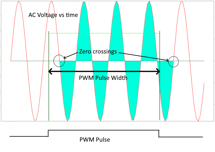
The PWM modulating wave frequency is a very low 0.6 Hz, or a period of 1.67 secs. This allows for 100 AC cycles and 200 zero crossings for the SSR. There really is no need to drive heater elements at a high frequency.
The relay wiring is modified as follows. The power indicator lamp pulses during operation to indicate the SSR operation.
A software PID controller drives the SSR to provide fine control for the heating. The goal is to use PID to select the correct power to get quickly to the desired temperature and stay there. The following calculations are performed each second to determine the SSR duty cycle.
1. Temperature Error (in degrees F) = Set point temperature - Current oven temperature (aka Process value). The last 10 error values are saved in a list.
2. Proportional Wattage = Kp * Error
3. Integral Wattage = Ki * sum(errors over last 10 readings)
4. Differential Wattage = Kd * (Current error - average(error over last 3 readings))
5. DeltaT = min(Current oven temperature, Set point temperature) - ambient temperature. This value helps calculate the adjustments for heat leakage.
6. Conduction heat leakage = KConduction * DeltaT. Strictly speaking, the conduction value should use the current oven temperature, not the Set point, but that would encourage overshooting.
7. Convection heat leakage = KConvection * fan speed * DeltaT. The thinking here is that the fan is ejecting some heated air and replacing it with outside air at ambient temperature.
8. Required wattage = Proportional + Integral + Differential + Conduction heat leakage + Convection heat leakage
9. Max available wattage = depends on current relay settings (see table above)
10. SSR Duty Cycle = Required wattage / Max available wattage. The duty cycle value computed is limited to a range of 0 to 1.
The error history list, typically the last 10 error values, is cleared when the set point is changed.
The SSR is also turned off momentarily while the relays are changing positions. This may help prevent arcing in the relays.
The SSR has a bit of a leakage that causes the neon lamp to glow even when the SSR is turned off with a zero duty cycle. A 22k resistor is added to drain the leakage and drop the voltage so that the neon light does not come on while the toaster is not operating.
Tuning the PID
Tuning involves setting values for Kp, Ki and Kd with a lot of trial and error, mostly errors. Making temperature charts helps develop the needed intuition.
· The Proportional coefficient needs to be large enough to reach the set point swiftly, but not overshoot it excessively.

· The Integral coefficient also needs to be large enough to reach the set point, but not cause oscillations.
· The Differential coefficient helps stabilize the temperature near the set point.
· The power needed to maintain a steady state at various temperatures was used to estimate KConduction .

· Similarly, the heater power needed to maintain steady state at the three fan settings was used to estimate KConvection.
· The coefficients are stored in a configuration file and can be modified via a web API.
· There was an issue with the oven tray blocking heat from the lower elements. The tray extended end to end and created a separate thermal zone below it, where the temperature was much higher than above it. This caused the PID system to have significant overshoots during warm ups. The PID system would try to home in to the correct temperature, but the extra heat from below would cause an overshoot. The chart below shows the problem. Using a smaller tray on the grill, or turning the fan on, equalizes the temperatures and eliminates overshooting.

Pinouts
It is important to plan ahead to map out the pins needed to control all the sensors and devices. The information below is not useful, but note the level of detail recorded. The Pi dedicates a few pins to specific functions, like SPI and PWM. These pins are allocated first.
|
Relay Module |
|
|||
|
GPIO |
Pin |
Ribbon |
Function |
|
|
22 |
15 |
Brown |
serializer: Upperin + Upper out |
|
|
23 |
16 |
Red |
serializer: Lower + Upper out |
|
|
24 |
18 |
Orange |
Inside light |
|
|
25 |
22 |
Yellow |
Heater, upper inner |
|
|
12 |
32 |
Green |
Heater, lower |
|
|
16 |
36 |
Blue |
Heater, upper outer |
|
|
20 |
38 |
Purple |
Fan, high |
|
|
21 |
40 |
Grey |
Fan, Low |
|
|
GND |
6 |
Black |
Relay Board |
|
|
GND |
20 |
White |
ULN |
|
|
VCC |
4 |
Brown |
ULN 5vdc |
|
|
Solid State Relay |
||||
|
GPIO |
Pin |
Ribbon |
Function |
|
|
18, PWM0 |
12 |
Red |
SSR + |
|
|
GND |
14 |
Orange |
SSR - |
|
|
Sensors |
||||
|
GPIO |
Pin |
Ribbon |
Function |
|
|
2 |
3 |
Grey |
Door |
|
|
3 |
5 |
Purple |
Light Switch |
|
|
4 |
7 |
Green |
Toaster Timer |
|
|
17 |
11 |
Yellow |
Oven Timer |
|
|
27 |
13 |
Orange |
Thermostat |
|
|
GND |
9 |
Blue |
Common to sensors |
|
|
Thermometer 6675 |
||||
|
GPIO |
Pin |
Ribbon |
Function |
|
|
vcc |
17 |
White |
+VDC 3.3 |
|
|
10 |
19 |
MOSI, NOT USED |
||
|
9 |
21 |
Blue |
MISO, SDO |
|
|
11 |
23 |
Grey |
Clock |
|
|
8 |
24 |
Purple |
Chip select 0 |
|
|
GND |
25 |
Black |
GND |
|
|
7 |
26 |
Chip select 1, NOT USED |
||
|
Piezo |
||||
|
GPIO |
Pin |
Ribbon |
Function |
|
|
19, PWM1 |
35 |
Red |
Piezo |
|
|
GND |
39 |
Black |
||
|
Capacitors |
||||
|
GPIO |
Pin |
Ribbon |
Function |
|
|
Vcc |
1 |
xx |
3.3v |
|
|
Vcc |
2 |
xx |
5v |
|
|
GND |
6 |
xx |
Gnd |
|
API
The toaster runs a web server that accepts commands and responds with requested information. The base URL and port number for the server are specified in a config file.
|
Method |
Path |
Args |
Results |
|
GET |
/values |
none |
{current operation values} |
|
GET |
/config |
none |
{current configuration values} |
|
GET |
/program |
none or programName |
{program: [[...], ...]} |
|
GET |
/record |
fileName |
recorded data […] |
|
GET |
/plot |
none |
temperature plot of last operation |
|
GET |
/home |
none |
web home page |
|
POST |
/program |
{'program': [steps]} |
OK |
|
POST |
/speech |
{'speech': 'spoken sentence'} |
Response to speak back '|' Accepted parameters |
|
POST |
/cancel |
force:true (optional) |
OK |
|
POST |
/record |
fileName |
Start recording temperatures |
|
POST |
/save |
programName |
Save current program |
|
PUT |
/config |
{config stuff} |
OK |
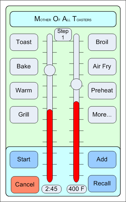
The New User Interface
The toaster can be operated in ‘compatible’ mode by manually turning on either of the two dial timers. This will start the oven or the broiler at the temperature set on the dial thermostat. The oven light will come on while the timer is active. The light button has been repurposed to control the fan. Double clicking this button will run the fan at High. The GUI based functions described below are enabled when the manual timers are not engaged. Turning on a timer while another function is running will set off a dreadful alarm. In this mode, the dial thermostat tells the software when to turn the heater elements on and off. This reproduces the original behavior and continues to be bad.
The toaster has a browser based GUI that connects using the API. It can be controlled from any browser, on a mobile phone, or desktop. Normally, one would select one of the functions; select a temperature and duration and press ‘Start’. The dial thermostat and timers will be ignored while in this mode. The available functions are listed below. As a convenience, when a function is selected, the toaster will remember the previously used temperature, duration and fan settings.
|
Function |
Usage |
Elements |
Fan |
|
Toast |
Max heat from above and below |
Lower + Upper in |
Off |
|
Bake |
Steady heat from above and below |
Lower + Upper Out |
Off |
|
Air Bake |
Convection baking |
Upper Out + Upper In |
Low |
|
Warm |
Gentle heat from above and below |
Lower + Upper Out |
Low |
|
Broil |
Max heat from above |
Upper Out + Upper In |
Off |
|
Air Fry |
Convection frying |
Lower + Upper Out |
High |
|
Air Dry |
Dry meats and vegetables |
Lower + Upper Out |
High |
|
Preheat |
Reach set temperature, up or down, ASAP |
Lower + Upper Out |
Off |
|
Grill |
Heat from below |
Lower |
Off |
|
Ramp |
Reach set temperature over selected duration |
Lower + Upper Out |
Off |
|
Pause |
Wait for specified duration or time of day |
None |
Off |
The oven light will come on while any function is active, including Pause. The power lamp will blink when the SSR is modulating power to the elements. The screen will display the set points for the temperature and duration, and also the current temperature and the elapsed time. These values will be updated every 5 seconds. The sliders can be modified at any time during operation, but the ‘Start’ button must be hit for the change to take effect.
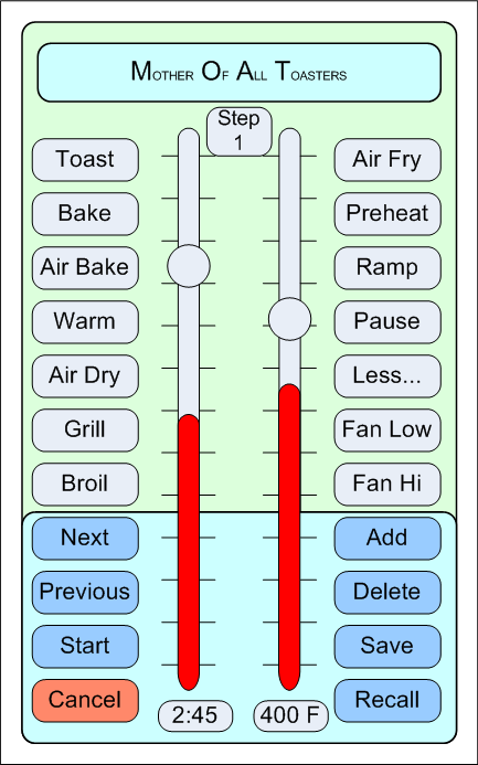
The toaster supports a ‘program’ feature, where a sequence of ‘steps’ can be set. Each step comprises a function, duration, temperature and fan setting. Pressing the ‘Add’ button will insert a new step after the current one. The ‘Next’ and ‘Previous’ buttons allow browsing up and down the list so that settings can be changed. The step index will be displayed. Clicking ‘Start’ will start the program. If the program was already started, then ‘Start’ will update the program on the toaster. ‘Cancel’ will stop any running function or program. The ‘Save’ button will save the current program under a specified name, while the ‘Recall’ button will load a previously saved program. The ‘Configure’ screen allows for Setting the time zone, preferred language, temperature scales, mobile number for SMS, buzzer tones, passwords, etc. The ‘Preheat’ function will end as soon as the specified temperature is reached, and the next step in the program will be started.
This is not your granny's toaster. It can be programmed and operated remotely. You can have a conversation with it and an Alexa interface will be added soon. However, there is not yet a way to load/unload the food in it.
Software
The software (Python/JavaScript) is available at https://github.com/solopilot/Toaster. (Yes, a test private key is included.) The software deserves a whole separate write-up. A User Manual would be useful.
The voice interface (SpeechRecognizer and TextToSpeech) is a Kotlin app that runs on Androids (but not on Amazon Fire ☹ ). The source code is available at https://github.com/solopilot/MOAT. (Mother of all Toasters)
Costs
|
Component |
~Cost |
|
Raspberry Pi |
$15 |
|
SSR |
$10 |
|
Relay board |
$10 |
|
ULN 2803A |
$3 |
|
5v Power supply |
$5 |
|
Thermocouple |
$8 |
|
Misc |
$15 |
|
Labor |
$0 |
|
Total |
$66 |
Conclusion
Given the temperature control and programmability, this gadget would be suitable as a solder reflow oven. However, the temperature rise and fall rates may not meet the requirements; they may be slow at about 0.8°C/sec. The SSR (Solid State Relay) allows great temperature control.
The wild temperature swings seem to be common for most retail products. Here is a plot from our new LG gas fired oven set to 350°F; it seems to swing between 350 to 450°F. I wonder how commercial ovens fare.
I tried adding a moisture sensor in the fan exhaust to detect the “doneness” of the contents. The idea was to stop heating at a specified moisture level. Perhaps my hygrometer was not adequately sensitive. I cannot find an inexpensive camera that is sufficiently heat resistant.
There are a number of expensive ($300-$500) smart ovens, but nothing comes close to this whiz bang gadget. The next step would be to make the spacing between the upper and lower heating elements adjustable programmatically. It would bring heat closer to the item being toasted.